cascoda-sdk-pages
Border Router Setup
This guide will walk you through everything you need to know to start using your KNX IoT Hub as a Thread Border Router.
Note: For the purposes of this guide, the KNX IoT Hub will only be used as a Thread Border Router. For that reason, it will simply be referred to as the “Border Router” from hereon.
Required Hardware
- Cascoda’s KNX IoT Hub (Border Router)
- 12V 1A Power Supply, with centre-positive barrel connector
- Ethernet cable
- A computer with an Ethernet socket
Initial Setup
- Connect one end of the Ethernet cable to the socket on the Border Router marked “PoE LAN1”, and connect the other end to your desktop computer.
- Connect the Power Supply to the Border Router.
- After ~30s, the Web GUI should become accessible. Navigate to http://openwrt.local
- Access the Web GUI by logging in as “root”, with an empty password field
You now have full control over your Cascoda Border Router.
We recommend that you change the hostname of your device by pressing System in the menu bar and selecting System from the dropdown menu. The default hostname is “OpenWRT”, which makes the device accessible via http://openwrt.local. Type in your desired hostname in the “Hostname” field, then press “Save & Apply”. This will change the URL that you use to access the Web GUI, and make it convenient to use multiple Cascoda Border Routers. This change will take effect once the Border Router is restarted.
You may change the login password by navigating to System - Administration from the menu bar.
Thread Administration
To access the Thread administration page, navigate to Network - Thread using the menu bar. Here you may create a new network or scan for existing networks, join an existing network & commission other devices. After forming or joining a network, you may also view the currently connected Thread devices by pressing the View button next to the Thread network, and then navigating to the Topology Graph page.
From the Thread administration page, you can also obtain the Thread Network Key for the network that you have created (sometimes also referred to as master key). To do this, click on the Edit button for that network; this will open a new page. Scroll to the very bottom of the page, and you will find the key in the input field that says Network Key (be careful not to accidentally edit it!).
Generate the Pre-Shared Key (PSKc)
If you would like to use external commissioners (e.g. a mobile Thread Commisioning App), you will need to generate a Pre-Shared Key for the Commissioner. This can be found System - Custom Commands. Press the “Run” button under the “Generate the PSKc” section without entering any arguments in order to see the syntax for using this command.
# /usr/sbin/pskc
pskc - compute PSKc
SYNTAX:
    pskc <PASSPHRASE> <EXTPANID> <NETWORK_NAME>
EXAMPLE:
    pskc 654321 1122334455667788 OpenThread
The PASSPHRASE argument is an alphanumeric password of your choice that will need to also be entered into the external commissioner. The EXTPANID & NETWORK_NAME must match the options entered in the Network Formation form.
Configure multicast addresses (important for KNX IoT)
In order to route KNX-IoT S-Mode messages into and out of the Thread network, it is necessary to manually configure the multicast routes according to the needs of your installation. This can be done from the Web GUI, within System -> Custom Commands.
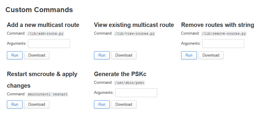
The add-route command is used for adding a new multicast route between the Thread and Ethernet & WiFi interfaces. The command takes two space-separated arguments. The first one is the IPv6 prefix to route, and the second one is the length of the prefix. For example, to add a route for ff35:30:fd00:0:10::/80, you must call add-route with arguments set to ff35:30:fd00:0:10:: 80. This will result in the following routes being added:
mroute from br-lan source fd82:7c67:3ec9::/48 group ff35:30:fd00:0:10::/80 to wpan0
mroute from wpan0  source fd82:7c67:3ec9::/48 group ff35:30:fd00:0:10::/80 to br-lan
The view-routes command is used to display the currently configured routes.
The remove-routes command iterates through the configured routes and removes each route containing the string passed as an argument. For example, runnning the command with the argument set to “fd00:0:10” would remove the routes added in the previous example:
# /lib/remove-routes.py "fd00:0:10"
Removing ' mroute from br-lan source fd82:7c67:3ec9::/48 group ff35:30:fd00:0:10::/80 to wpan0'...
Removing ' mroute from wpan0  source fd82:7c67:3ec9::/48 group ff35:30:fd00:0:10::/80 to br-lan'...
Note that these changes will not take effect until smcroute is restarted. This can be accomplished with the Restart smcroute custom command, but also by restarting the Border Router.
Ethernet Configuration
By default, the Border Router is set up to be connected in a tree topology. This is accomplished through the firewall & IP addressing configuration. The Ethernet socket labeled PoE / LAN1 should be connected directly to the PC, while the socket labeled WAN / LAN2 should be connected to a network having access to the Internet.
The firewall configuration can be viewed & modified by navigating to Network - Firewall. The firewall is configured to block most communication directed towards the WAN / LAN2 interface, except for specific protocols such as IGMP. By contrast, the firewall is significantly more permissive of messages arriving through the LAN1 interface. If communication with devices on the WAN is desired, this should either be initiated from a device living on the LAN1 or Thread interface, or alternatively a new firewall rule must be created to allow bidirectional communication on that interface.
The Border Router acts as a DHCP & DHCPv6 client on the WAN interface, and it expects to receive IP addresses from upstream routers. On the local LAN1 interface, the border router acts as a DHCP & DHCPv6 server, and is responsible for assigning IP addresses to downstream devices. It also generates a random /48 ULA prefix for downstream IPv6 devices.
Firmware Upgrade
In order to upgrade the border router firmware, navigate to System - Backup / Flash Firmware. You may upload the new image using the “Flash image…” button near the bottom of the page.